Home Breaker Box Wiring
220 Volt Breaker Wiring Diagram
Step 2: Wire Connections. Make the wire connections for the circuit to be GFCI protected as follows: Connect the hot wire from the circuit directly to the GFCI input (brass terminal). Connect the white wire from the circuit to the GFCI breaker's load neutral (silver terminal). Video | Schneider Electric.
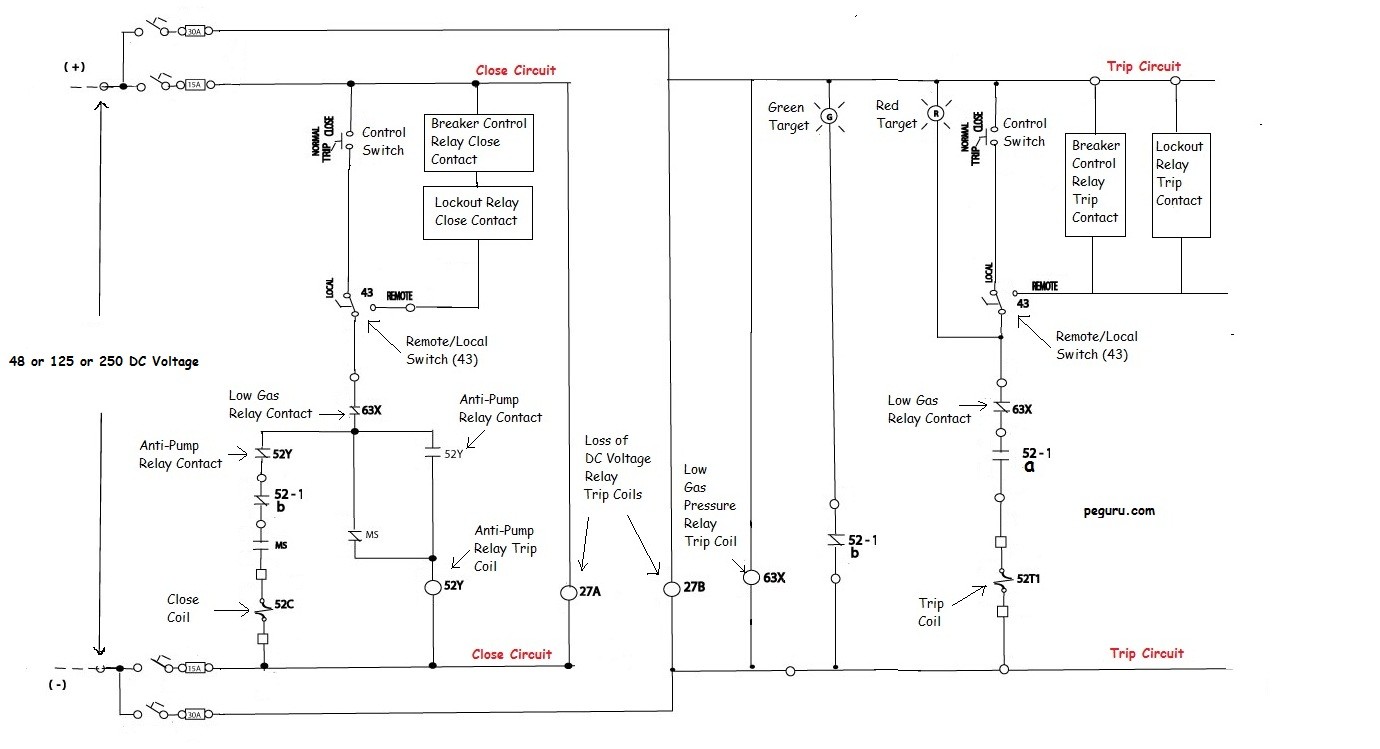
Power Systems Engineering Power Circuit Breaker Operation and
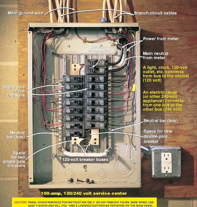
Together, these three wires exit the breaker box and go on to provide the juice for their designated circuit. Single Pole: These consist of one switch, handle 120 volts, and can be either 15 or 20.

12v Circuit Breaker Wiring Diagram Panel Breaker Bluesea Sea Circuit
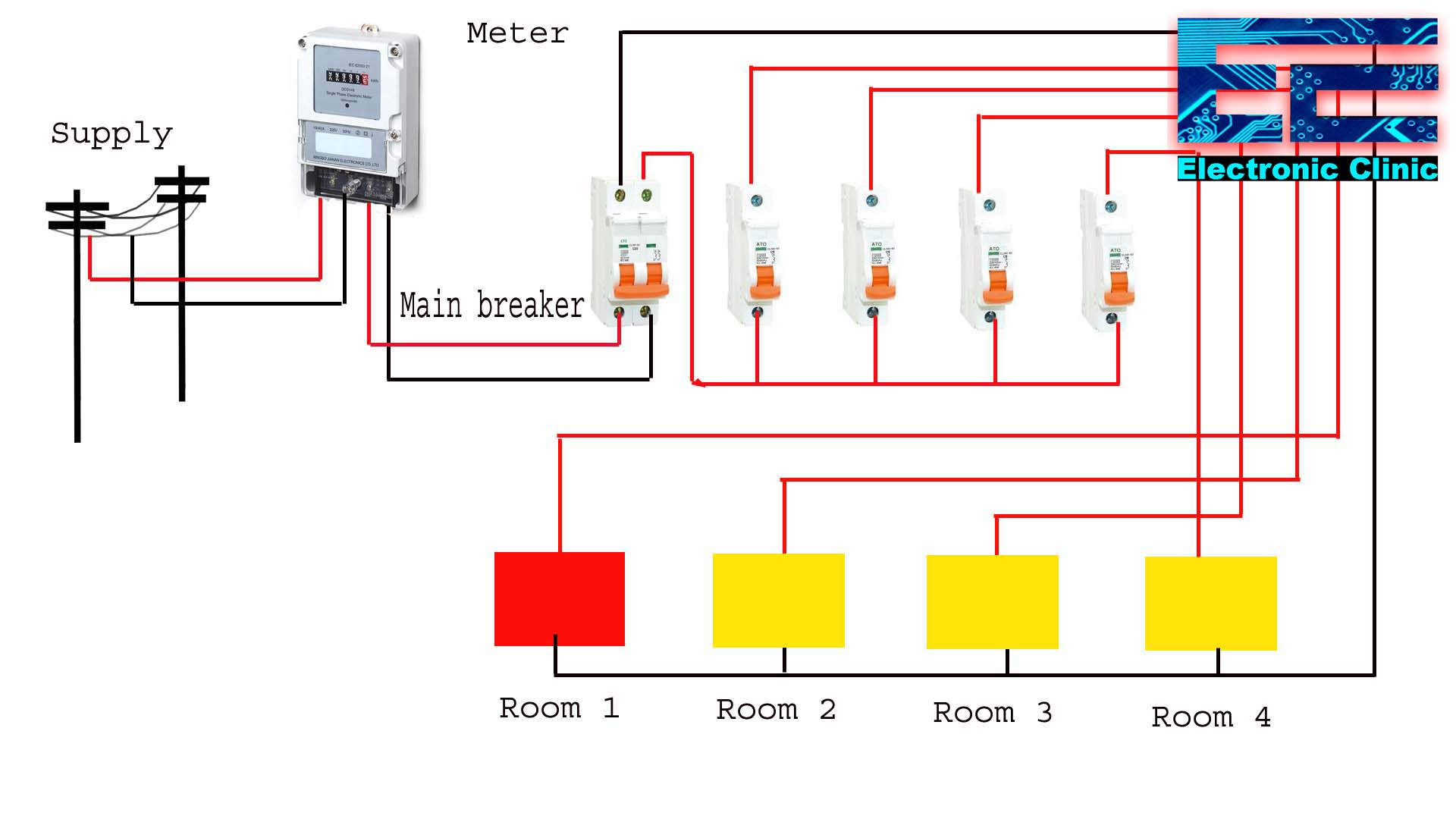
The wiring diagram of a circuit breaker panel shows how all the electrical components are connected and how the power flow is distributed. It includes the main breaker, which controls the power supply to the entire panel, and individual circuit breakers that control power to specific circuits or appliances. The diagram also shows the grounding.

200 Amp Breaker Panel Wiring Diagram Wiring Diagram
For now, you simply need to identify a space where you can install the circuit breaker. 3. Remove the electrical panel cover. Use a screwdriver to remove 3 of the screws supporting the cover. Then, use 1 arm to hold the panel cover in place as you unscrew the last screw. Finally, pull the cover away from the panel.

Circuit Breaker Wiring Diagram Australia
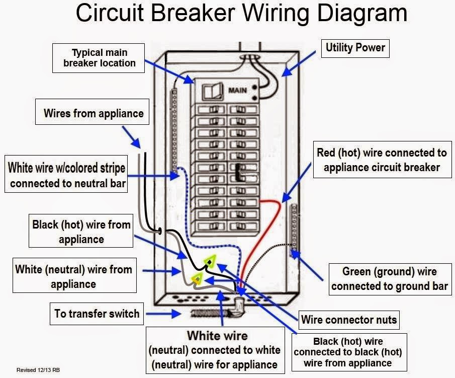
Use a wire stripper to remove a 1/2-inch of insulation from the white neutral wire. Insert the end of the neutral wire into an open terminal on the neutral bus bar and tighten the screw. Make sure you put only one wire under each open terminal. Strip away a 1/2-inch of insulation from the black hot wire.
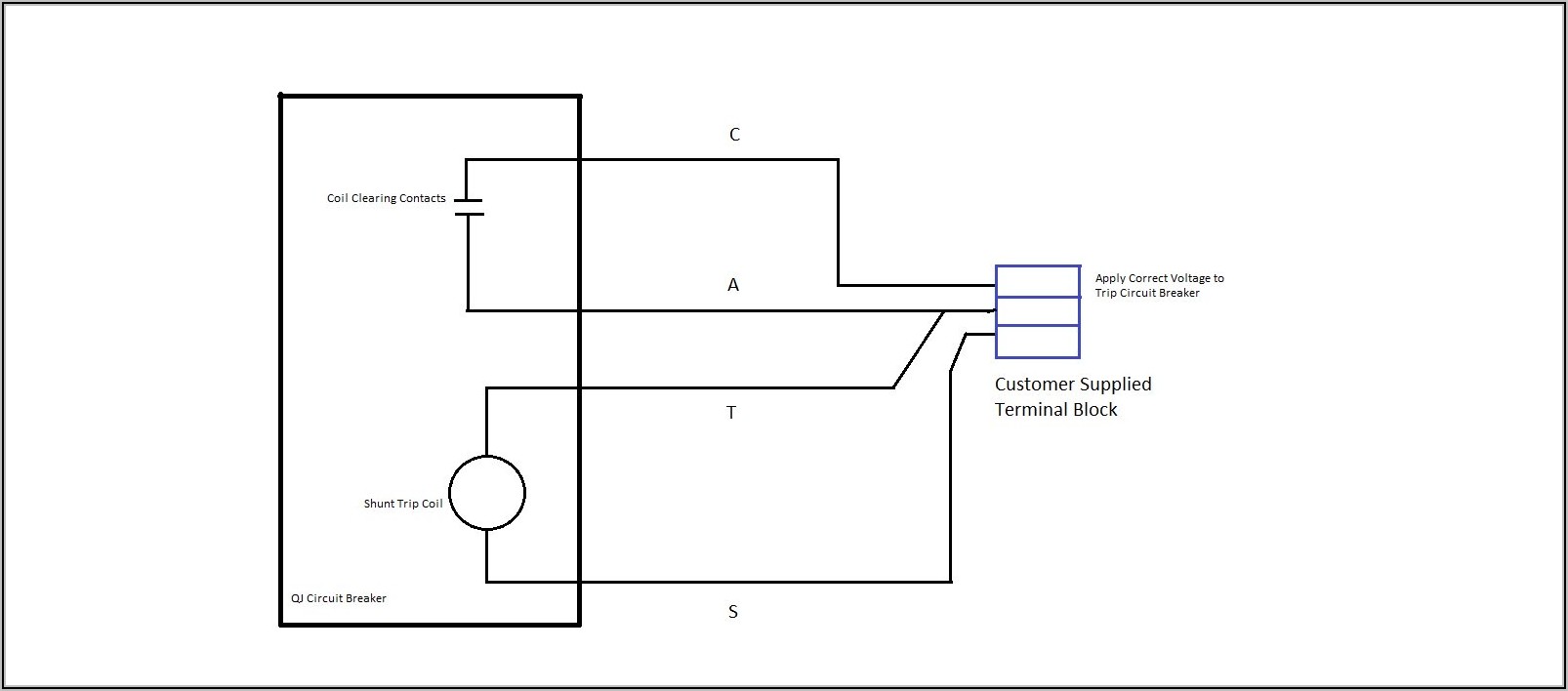
Shunt Trip Circuit Breaker Wiring Diagram Diagrams Resume Template
Snap the one-pole breaker onto a hot bus 3. The heel of the breaker seats on a plastic cleat and then pivots so that its jaws engage a metal bus sticking up. Press down to seat the breaker securely. Strip 3⁄8 in. to 1⁄2 in. of insulation from the end of the hot wire, then connect it to the lug screw on the end of the breaker 4.

Seriously! 41+ Little Known Truths on Eaton 50 Amp Gfci Breaker Wiring
With the appropriate 10 gauge wire, the right breaker, and a compatible receptacle, installing a 30 amp breaker and its circuit can be your DIY project. Follow this guide for more details. Table of Contents.. Check the wiring diagram when wiring a 30 amp receptacle. A 10-3 cable for 240 volts will have two hot wires, one neutral, and one.
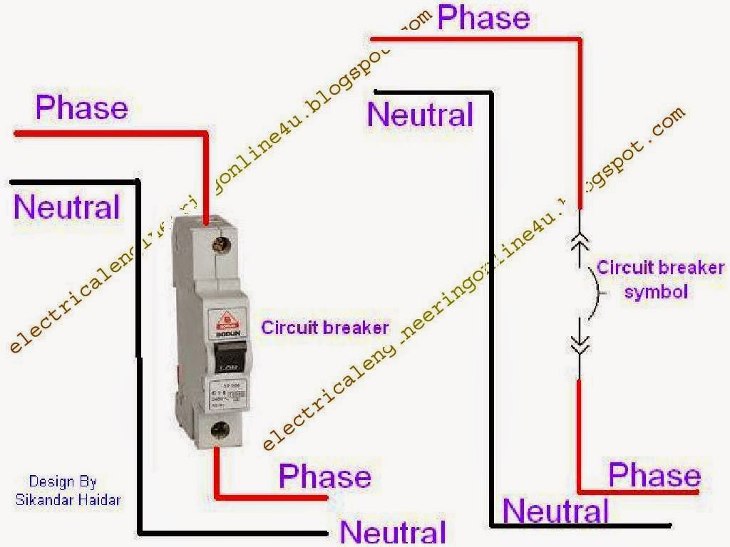
How To Wire A Circuit Breaker Electrical Online 4u
Learn how to create and interpret circuit breaker diagram wiring diagrams. Understand the functions and symbols used in these diagrams, and get tips on troubleshooting electrical circuits.. In order to properly wire a circuit breaker, you will need basic tools such as wire cutters, wire strippers, electrical tape, and a screwdriver. It is.
Wiring a Breaker Box Breaker Boxes 101 Bob Vila
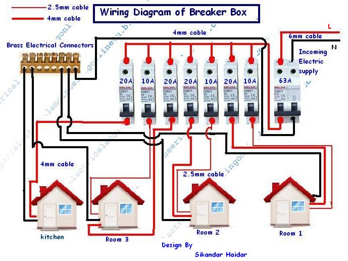
This circuit breaker wiring diagram illustrates installing a 20 amp circuit breaker for a 240 volt circuit. The 12/2 gauge cable for this circuit includes 2 conductors and 1 ground. The white wire is used for hot in this circuit and it is marked with black tape on both ends to identify it as such. A neutral wire is not used in this circuit.

Home Breaker Box Wiring
Connect the Hot Wires. Connect each hot circuit wire to one of the terminals on the new 240-volt circuit breaker. Depending on how the circuit has been installed, these might be two black wires, a black and a red wire, or a black wire plus a white wire marked with black tape to identify it as a hot wire. Make sure to insert the wires fully into.
Simple Circuit Breaker Diagram »
Wiring Diagram Examples. The best way to understand wiring diagrams is to look at some examples of wiring diagrams. Click on any of these wiring diagrams included in SmartDraw and edit them: Wiring Diagram - Auto Wiring Diagram. Browse SmartDraw's entire collection of wiring diagram examples and templates.

2 Pole Gfci Breaker Wiring Diagram Free Download Wiring Diagram Schematic
Cut the wire to length so that 20cm (8") sticks out of the outlet box, and about 80cm (30") sticks out at the electrical panel. [4] 7. Cut about 15cm (6") of the (usually yellow or gray) outer jacket away from the wire, being careful to not damage the inner black or white jackets.
How To Wire And Install A Breaker Box Electrical Online 4u
There are three basic types of wiring diagrams: Wiring: Depicts electrical devices as drawings or pictures connected by lines representing wires. Wiring diagrams show specific electrical connections. Pictorial: Shows how components are related to others on the same circuit, but contains less detailed information about electrical connections.

[DIAGRAM] 20 Double Pole Switch Wiring Diagram Schematic
Step 3: Use a 120/240-volt two-pole breaker that connects to two 120-legs. Step 4: Connect the green wire to the green outlet slot. Step 5: Ensure at least one box in your line is grounded. Step 6: Choose a 20- or 30-amp, 250-volt outlet. Step 7: Test the system before using any machines. Step 8: Add protective covers and label the outlets.

Square D Gfci Breaker Wiring Diagram Free Wiring Diagram
Steps. Download Article. 1. Switch off the main power switch. This should be located at the top of the breaker panel. 2. Take the cover of the breaker box off. 3. Use an electrical tester by putting the tip of one probe against the ground bus bar and the other against one of the screws of a circuit breaker.
29 Circuit Breaker Box Diagram Wire Diagram Source Information
Remove the panel box cover plate knockout that corresponds to the slot where you installed the new breaker (bend it back and forth until it breaks off). Then install the cover and turn on the main breaker. Switch the new AFCI to "ON.". Wait a few seconds and press the "TEST" button. The breaker should trip.
